Orange Cryostat Cooldown Procedure
For some general remarks on cryogenic handling at the Neutron guide hall see . .
Preparation
This is normally done by a sample environment technician
- Pump main vacuum through valve (V) with a turbo pump, ideally over night. If the cryostat
was cold recently a few hours will be o.k., but if water might be condensed inside,
it should be pumped for several days.
- Connect sample space, helium reservoir etc. (all volumes which will contain liquid
or gaseous helium) with a raw vacuum pump. Flush 2 times with helium gas. Check
the function of cold valve (C) and warm valve (W). Pump sample space.
- Fill in liquid nitrogen. Ideally wait one night.
- Fill in liquid helium.
OrangeCryostatTopPictures
Insert Sample
- Increase the temperature of the heat exchanger to 100 K. (The better part of air will not condense at this temperature)
- Connect a helium gas tube to the sample space and wait until 1 bar is reached inside.
- Remove cover.
- Enter the sample stick slowly and screw the top.
- Pump down and flush again with He gas. To remove all contaminants you should repeat this procedure an infinite number of times (at least 2x).
- If you cannot reach 0 mbar (or -1 bar) on the mechanical gauges you might be faced with a leak into the sample chamber or with an offset on the gauge.
- Pump down to a pressure between 10 and 50 mbar.
Cool Down
- Connect helium pump to the pumping port (P). Switch on the pump and wait until
the pressure stabilizes (should be less than a few millibars). Make sure that
the warm valve (W) is closed, open cold valve (C) a little, the pressure at the
pump should not exceed 20 mbar (30 on a maxi cryostat).
In SEA, this could be done by switching the needle valve control to automatic
and set 20 - 30 for the flow maximum.
- Put a setpoint of 10 K on the heat exchanger.
- When the heat exchanger is at 10 K and the sample near 10 K, reduce the pressure
by closing the cold valve gradually until the heating power the temperature controller
needs to keep 10 K has reached a value between 100 and 200 mW.
With SEA, the regulation of the needle valve is done automatically, but the value
for "flow set" should be optimized if not known from an earlier run.
- Put the temperature setpoint to zero. The cryostat should cool to 1.6 K within 10 minutes.
If the base temperature can not be reached or the "nv_Set" is oscillating, most probably
the value for "flow set" was not determined properly, and must be increased slighly.
Cool Down with warm valve
In principle there is the possibility to cool down with the use of the warm valve,
without He pump. As this is not recommended, it is mentioned only for information.
Make sure that the warm valve is always closed except for preparation.
Remove Sample
- Increase the temperature of the heat exchanger to 100 K.
- Connect a helium gas tube to the sample space and wait until 1 bar is reached inside.
- Remove the stick slowly and put the cover.
- If no new sample is entered soon, pump down the sample space to at least 10 mbar.
- Dry the sample stick with a hair blower (not a hot gun!)
He Flow Schematics
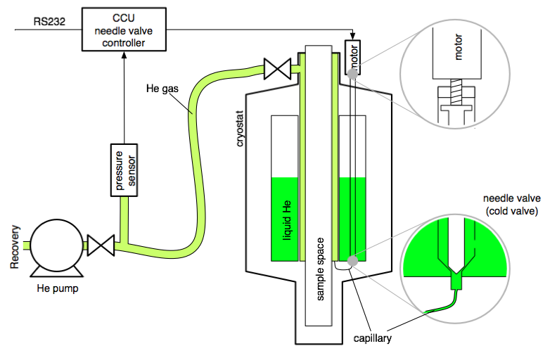
Automatic Cryostat Control and Monitoring
All our cryostats are monitored and controlled with SEA.
All instruments are equipped with a temperature controller (Lakeshore 340) for the temperature control
and a cryostat control unit (CCU) for the control of pressures, levels and valves.
The CCU will only work with a correctly configured SEA instance. It can read the pressure in the Helium gas pumping line and set the needle valve accordingly.
It reads the analog output of AMI Helium level meters and serves as a level indicator for our 2 point liquid Nitrogen level meter.
The Unit is used to energize the electromagnetic valves involved in the automatic Nitrogen/Helium refill.
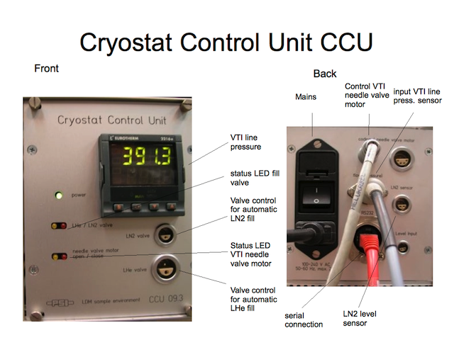
Attachments:
CCU.png
NeedleValveControl.png
Printer Friendly
Page Info
This page last changed on 08-May-2012 10:43:57 UTC by Bartkowiak.
|
