The cryomagnetic system consists of a superconducting split coil magnet which is mounted inside a cryostat with vertical field axis. Neutron access to a sample positioned at the centre of the magnet is possible through the split of the magnet throughout 340 degrees. Two modes of operation of the magnet are possible; symmetric to 9 tesla at 2.2 Kelvin and asymmetric to 4 tesla at 4.2 Kelvin.
For a VTI section drawing see MA09Drawings.
Samples are introduced into the system on a sample holder from above. The temperature of the sample can be controlled within the temperature range of 1.5 to 300 K in the variable temperature sample insert (VTI). An additional feature of the variable temperature insert is a static exchange gas sample tube which can be inserted into the dynamic exchange gas sample space. Alternatively a separately acquired Heliox low temperature insert may be fitted into the VTI sample space.
The magnet is joined to a vacuum insulated low loss cryostat by two indium sealed flanges. The cryostat incorporates the magnet quench protection circuit and the magnet and cryogenic services.
The magnet has a pair of superconducting switches to allow it to be operated at a constant field with no external supply of current. A lambda point refrigerator is fitted to allow magnet operation at 2.2 Kelvin.
The drawing of the system accompanying this manual should be consulted in conjunction with the description given in the following pages.
Ancillary equipment accompanying this system, namely:
The cryostat is an Oxford Instruments low loss type cryostat. It is of a vacuum insulated, all metal construction and features a full length liquid nitrogen cooled radiation shield. The materials used in the construction are as follows:
| Outer vacuum case (OVC) | aluminum alloy body and tails stainless steel top plate |
| Liquid nitrogen reservoir | aluminum alloy |
| Liquid helium reservoir | stainless steel |
| Spacers | glass fibre |
The liquid nitrogen reservoir and liquid helium reservoir are of all welded construction. The outer vacuum case (OVC) has a welded body, but has an "O" ring seals to allow access to the internal parts of the cryostat and to assist the installation of the Variable Temperature Insert (VTI).
The VTI and its radiation shield are removable from the top of the cryostat. No access is available to the magnet as it is welded into the helium reservoir. Glass fibre spacers are used to support and maintain position of the complete assembly, while minimising heat influx. Multilayer superinsulation is used on both the helium reservoir and the radiation shield to minimize radiate heating.
All services to the helium reservoir are mounted at the top end of the three service necks and on the cryostat top plate.
These services comprise :
The siphon entry port has an associated cone located within the cryostat to ensure correct alignment. A tube runs from the cone to the lower chamber of the magnet, and ensures that helium filling is from the bottom of the system. Al1 ports should be sealed with the plugs provided when not in use.
Electrical access to the magnet is provided in the form of two coaxial magnet terminal posts; one post for symmetric energisation (on the long services neck with the VTI needle valve), the other for asymmetric energisation (on the short services neck with the syphon entry). Four ten pin connectors are fitted to the cryostat which have wiring for the persistent mode switch heaters, the VTI, helium level probe, and carbon resistor temperature sensors on the magnet.
The remaining cryostat services are the evacuation/vent valve mounted on the cryostat top plate, nitrogen fill/vent ports; one of which is fitted with a one way valve to prevent total blockage if air is sucked back into the nitrogen jacket through the other ports. The cryostat is fitted with a pressure relief valve which would operate in the event of a cryogen leak into the vacuum space.
The exhaust ports from the service necks are manifolded together for connection to a helium recovery line. The manifold incorporates a safety valve to relieve pressure in the event of a magnet quench into a blocked recovery line.
A ten pin seal on the cryostat top plate carries wiring to the VTI needle valve heater and sensor.
The magnet is composed of two sets of superconducting coils. They are built onto a stainless steel structural formers separated by aluminium rings to resist the large attraction forces between the coil blocks. The field and bore axes of the magnet are vertical.
For a coil section drawing see MA09Drawings.
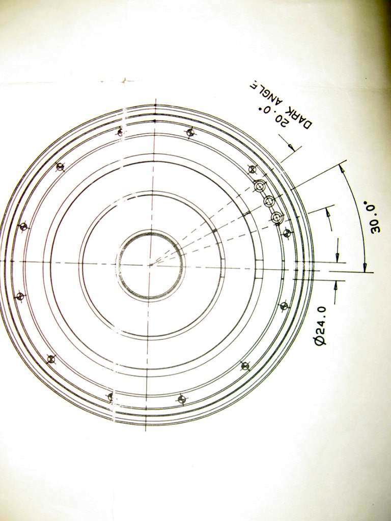
The vertical bore is occupied by the variable temperature insert into which samples can be loaded. Transverse access for neutrons is provided through 340 degrees through the magnet, VTI and cryostat; the remaining 20 degrees is used for cryogenic services. Please refer to the drawings accompanying this manual for the position. At the beam entry point holes are drilled through the magnet former to allow maximum neutron transmission.
Two modes of energisation are possible; symmetric which energizes all the coils to generate flux densities up to 8 tesla at 4.2 Kelvin and 9 tesla at 2.2 Kelvin. Also asymmetric which energises selected coils to generate flux densities up to 4 tesla at 4.2 tesla.
Niobium Titanium superconductor is used for the magnet coils. The wire is of a multifilamentary, copper stabilized design. All sections are constructed to the MAGNABOND system to form a matrix that is both physically and cryogenically stable under the considerable Lorentz forces generated during operation. All the constituent sections of the magnet are connected to allow series energisation.
The magnet is equipped with two superconducting switches, one for each of the two modes of possible energisation. The superconducting switches consist of a length of superconducting wire non-inductively wound with a wire electrical heater. The superconducting switch has the length of superconductor wire in parallel with the magnet sections to be energised. The superconducting wire is made resistive by raising its temperature using the heater. The switch is then in its open state and current due to a voltage across the magnet terminals will flow in the superconducting magnet windings in preference to the resistive switch element. The switch is in its closed state when the heater is turned off and the switch element becomes superconducting again.
The process of establishing persistent mode operation of the magnet consists of energising the magnet to give the required field with BOTH switches in the open state. The switches can then be closed and the current flowing through the leads reduced to zero, leaving the magnet in its previously energised state. The current flowing in the magnet windings remains constant as the magnet lead current is reduced, the current flowing in the closed switch then being the difference between the magnet and lead currents.
Protection resistors are provided in series with diodes for all magnet sections, restricting the development of potentially high voltages in the event of a
magnet quench (rapid conversion from the superconducting to the normal resistive state). The resistors also dissipate some of the energy stored in the magnet, thereby reducing the energy dissipation within the magnet windings. The resistors are mounted on plates attached to the magnet in the helium bath of the cryostat. Connections between the magnet and the cryostat are made by electrical connectors and solder joints at indium sealed flange level just above the magnet.
Barrier diodes are used in the protection circuit so that under limited voltage conditions, e.g. energisation, all the current passes through the magnet. Under quench conditions, the barrier voltage is exceeded and the protection circuit shunts a proportion of the current away from the magnet windings.
The variable temperature insert ( VTI ) is of the dynamic exchange gas type, but has an optional center tube that can be fitted to convert it to a static exchange gas type. The sample space region is made from aluminum to allow low impedance to the neutron beam.
The VTI operates over the temperature range 1.5K - 300K, using dynamic flow of helium liquid or gas through a heat exchanger below the sample position. The temperature range can divided into two regimes each requiring a slightly different mode of operation.
a) 1. 5K - 4.2K
Temperatures between 1.5K and 4.2K may be obtained by allowing liquid helium to collect in the heat exchangers and reducing its vapor pressure by over pumping. The heat exchangers can be filled with helium from the main reservoir using the VTI needle valve situated on one of the service necks. In this case, temperature control can best be achieved using the pressure controller/monastic device to maintain a referenced pressure over the liquid.
b) 4.2K - 300K mode
Temperatures between 4.2K and 300K may be obtained by balancing the cooling power due to liquid helium flow into the heat exchangers, against the power input, due to a non-inductive heater on the heat exchanger. Temperature control is achieved by setting the helium flow rate, using the VTI needle valve and gas flow pumping system, in conjunction with the use of a temperature controller connected to the heater/temperature sensor mounted on the sample space heat exchanger.
A radiation shield surrounds the sample cell, the shield being connected directly to the nitrogen cooled radiation shield. The sample cell and radiation shields share the same vacuum as the cryostat OVC.
The sample is introduced into the sample space from the top of the VTI, mounted on a sample holder. The sample holder ideally should include a temperature sensor and preferably a small non-inductive heater to give close temperature control of the sample and to optimize thermal settling time.
Electrical access to the VTI heat exchanger heater and temperature sensors is made using the ten pin seal on the VTI top fitting, and a ten pin seal on the cryostat top plate to the needle valve heater and thermometer (blockage clearing).
The Lambda point refrigerator, shown schematically above, allows the temperature of the magnet reservoir to be reduced to 2.2K. The normal method of producing sub cooled helium would be to pump on the helium exhaust line, thereby reducing the vapor pressure of the helium and therefore its temperature. This has the disadvantage that all access to the helium reservoir is prevented, and all access ports have to be vacuum tight rather than merely gas tight, in order to prevent ice formation and contamination of the helium recovery system. Consequently it is not possible to refill the cryostat whilst operating at reduced temperatures.
The Lambda point refrigerator cools the helium around the magnet to 2.2K by conduction and convection, without any reduction of pressure in the reservoir. It consists of a needle valve fed from the main helium bath, and connected via a cooling loop to an exhaust port that exits the cryostat through the main bath. By pumping against the needle valve a cooling effect is produced. The loop then cools the surrounding helium by conduction. The cooler and therefore denser helium sinks to the bottom of the cryostat and is replaced by liquid 4.2K. The cooling continues until the Lambda point (2.17K) is reached, when a layer of superfluid helium accumulates at the bottom of the cryostat. The superfluid has an extremely high thermal conductivity and therefore contains no temperature gradients. The result is that there are two distinct helium phases (the normal and superfluid) with a temperature gradient only in the normal phase. Further cooling simply causes the above boundary to move further up the helium bath.
In order to monitor the temperature of the helium, carbon temperature sensors are provided above and below the magnet. Temperature is measured using an electronics multimeter on as high a resistance range as possible to avoid self heating of the carbon sensors.

Important:
The internal parts of the cryostat can be accessed for removal or refit of the VTI or for limited inspection of the cryostat suspension and superinsulation. No direct access is possible to the magnet or protection circuit as these are welded into their helium vessels; it is possible to separate the magnet from the cryostat as there are indium sealed flanges between the two items.
To gain access to the internal parts of the cryostat, release the vacuum in the OVC by opening the vac/vent valve to air or preferably dry nitrogen gas. Only do this if the system has been allowed to warm thoroughly to room temperature. A rubber tube connected to the valve with its free end immersed in liquid nitrogen is the best way to introduce an atmosphere of dry gas into the OVC, if no other supply is available.
Remove the screws that hold the OVC tail of the cryostat to the main OVC body. Lift the cryostat away from the OVC tail using a hoist.
Remove the radiation shield; this will allow access to the bottom of the VTI.
The VTI can be removed by separating the two halves of the small indium seal in the capillary line, the capillary can then be carefully straightened. Remove the screws that hold the VTI in place at the top of the cryostat and carefully extract the inner parts of the VTI upwards. Take great care not to bruise the wiring during extraction. Direct access is then available to the temperature sensors and the heater.
No further disassembly of the cryostat should be undertaken as all other parts are secured by welds.
Re-assembly is essentially the reverse of the above procedures. Points to note are:
In order to maintain the thermal isolation of the liquid helium, it is necessary that a high vacuum be maintained in the cryostat outer vacuum case (OVC). The recommended pumping equipment consists of an oil diffusion pump of 50mm diameter, fitted with a liquid nitrogen cold trap. The diffusion pump should be backed by a rotary pump of not less than 25 L/min pumping speed, fitted with a gas ballast facility. All connecting lines should have an internal diameter of not less than 1 5mm and be as short as possible. If plastic or rubber link tubes are used, these must NOT have been used previously to carry or pump helium when evacuating from atmospheric pressure.
If the cryostat is already evacuated and it is desired to inspect the pressure only, the pumping tube should be evacuated and the diffusion pump operating before the OVC valve is opened. If pressure is greater than 10-4 torr with the system warm, the cryostat should be evacuated overnight with the diffusion pump to less than 5 x 10⁻⁴ torr It is recommended that the cryostat is always pumped overnight before use.
4.2.1 Filling the liquid nitrogen container
Fill helium gas into the variable temperature insert sample space and heat exchanger and the lambda point refrigerator. Close off the needle valve of the VTI and lambda fridge to avoid contamination. A helium filled rubber bladder can be fitted to each space to give an idea of the pressure that exists within. In addition, the main liquid helium reservoir should also be evacuated and Evacuate and flush with dry flushed with dry helium gas to remove any residual moisture.
Connect one of the filler/vent tubes of the liquid nitrogen container to a storage vessel using flexible plastic pipe. Transfer the liquid nitrogen by pressurizing the storage vessel to approximately 0.25 atm. Violent boiling will occur initially until the radiation shield has cooled down. When liquid nitrogen sprays out of the filler tubes release the pressure on the storage vessel to stop the transfer
The storage vessel can be pressurized using a high-pressure gas cylinder fitted with a reducing valve. By using an electrically operated valve between the gas cylinder and the storage vessel, the liquid nitrogen container can be filled and the level maintained using a Liquid Nitrogen Level Controller.
Inspect the liquid nitrogen level daily.
The problems caused by ice formation in the filling tubes can be prevented by slipping 0.25 m lengths of plastic tubing over them. These tubes also prevent any overflow of liquid nitrogen from cooling the top flange and 'O' rings. This can be important if an auto filling system fails to stop the nitrogen transfer when the tank is full. At least one of the liquid nitrogen fill/vent tubes should be connected to a one-way valve (e.g. a Bunsen valve), as a precaution against ice blockage.
Important:
4.2.2 Precooling the Magnet
Before filling the cryostat with liquid helium, the magnet must be cooled to a temperature below 100K. This is done using liquid nitrogen. However the lambda point refrigerator and variable temperature insert must be pumped and flushed with helium gas before any liquid nitrogen is transferred into the helium reservoir. The lambda point refrigerator must be filled with helium gas at 760 torr and the needle valve closed during precooling. The respective exhaust line valve should also be shut. To transfer liquid nitrogen use a length of close fitting stainless steel tubing inserted into the transfer tube entry port.
Control the flow of LN2 to the helium tank, to slowly precool and thereby protect the magnet, by connecting a restriction to the cryostat exhaust line (e.g. the one way valve provided or 12 ins. of 0.25 ins. bore tube) and by transferring the LN2 at an over pressure of approximately 260 torr
Allow the liquid nitrogen to remain around the magnet for approximately 2 hours. To remove the liquid nitrogen from the liquid helium reservoir, insert the stainless steel tube into the reservoir's transfer entry fitting and ensure that it is firmly fitted in the cone mounted on the magnet support plate. Blow out the liquid nitrogen through the tube by over-pressurizing the liquid helium reservoir to not more than 200 torr (4 p.s.i.g.). Ensure that all the liquid nitrogen is removed. Failure to remove all the liquid nitrogen will make transferring liquid helium into the reservoir difficult and may impair the performance of the magnet.
When the liquid nitrogen has been removed, seal off any open access ports on the cryostat and evacuate the liquid helium reservoir using a rotary pump. If, during the evacuation process, a pause is seen in the pressure range 70 - 100 torr, then liquid nitrogen is still present and immediate action should be taken to repeat the blow out procedure, or alternatively, warm helium gas should be blown down the liquid nitrogen blow out tube to the bottom of the liquid helium reservoir, to evaporate the remaining liquid nitrogen. The helium reservoir should then be let back up to atmospheric pressure, with dry helium gas. Repeat the pumping and flushing procedure at least four times, in order to thoroughly purge the magnet of nitrogen. As an indication that all the liquid nitrogen has been removed, check that it is possible to evacuate the liquid helium reservoir to a pressure of less than 10 torr Finally, evacuate the liquid helium reservoir to a pressure of less than 1.0 torr, for approximately 15 minutes, before refilling the reservoir with helium gas.
Pump and flush the lambda point refrigerator with helium gas and check the operation of the needle valves after the liquid nitrogen has been removed.
4.2.3 Initial filling with liquid helium4
Connect the cryostat to the helium recovery system or put a one-way valve on the cryostat exhaust. Position the liquid helium storage vessel so that the transfer tube can be inserted easily into the port on the cryostat. Ensure that the transfer tube is not blocked by blowing helium gas through it.
Remove the plug from the transfer tube entry port and also from the top of the storage vessel. Insert the transfer tube slowly, allowing it to cool gradually. Ensure that the end of the transfer tube is fitted into the cone at the bottom of the services neck. In this way, liquid is introduced at the bottom of the magnet which is then cooled by the enthalpy of the gas as well as by the latent heat of evaporation.
Start transferring the liquid helium by pressurizing the storage vessel. (This is generally done by gently squeezing a rubber bladder full of warm gas attached to a port on the storage dewar top fitting). The transfer rate should be such that the vent pipe is frozen for not more than 2 m of its length. The initial transfer rate should be equivalent to about ten litters of liquid per hour. This rate can be increased as the magnet cools.
When the magnet resistance drops to zero, the transfer tube should be lifted slightly so that it is no longer in the cone. The transfer rate can then be further increased in order to fill the liquid helium container.
When the liquid helium reservoir has been filled, stop the transfer by releasing the pressure in the storage vessel. Remove the transfer tube and replace the plug.
Inspect the liquid helium level daily.
4.2.4 Refilling with liquid helium
The cryostat should be refilled before the level reaches the 10% mark as indicated by the helium level meter. In refilling, care should be taken not to evaporate the liquid in the cryostat with the hot gas which initially comes through the transfer tube. (N.B. Failure to take care can cause the magnet to quench). The correct refilling procedure is as follows:
(i) If the level is below 0% or if the user is not certain that a careful transfer can be done - DE-ENERGISE THE MAGNET - refill and then re-energise the magnet.
(ii) Refill the dewar, but be careful as the siphon is introduced and as the transfer starts.
Important:
The following instructions assume that an OXFORD INSTRUMENTS PS120-10 magnet power supply is being used. The instructions that follow are sufficient to cover the basics of running a magnet. For more detailed instructions and description, consult the power supply instruction manual. The PS120-10 allows operation of the magnet either manually or under control of a computer (using the RS232 link, or IEEE interface if the optional converter is fitted).
Important:
Pressing the SET POINT button on the SWEEP CONTROL panel (the switch heater is left 'off'). The current leads will be swept at a fast rate to the Set Point vale. Turn the switch heater current 'on' by pressing the HEATER ON button for five seconds until the indicator light remains on when the button is released.
Press the ZERO button on the SWEEP CONTROL panel and the magnet will start to de-energize. The Set Rate can be increased during the sweep without stopping. If it is desired to change the value of the magnetic field, sweep the current leads to the present current or field of the magnet, open the switch by turning on the heater. Press the SET POINT button and RAISE and LOWER to change the Set Point to the new desired value. Make changes to the Set Rate of sweep in a similar manner. Press the SET POINT button on the SWEEP CONTROL panel and the magnet will either energize or de-energize to the new field. If the voltage needed to drive the magnet at a given rate is such that the maximum voltage of the power supply will be exceeded, the power supply will deliver its full voltage and the RATE LIMITING light will illuminate, on the SWEEP CONTROL panel. The sweep will continue, but at a slower rate than intended. In the event of a magnet quench, the power supply will trip to zero amps and the QUENCH light will illuminate.
Important:
A pump of minimum 1000 I/min. (60 m3/hr) displacement should be connected to the pump exhaust port, as shown overleap. The pressure gauges should be connected to the exhaust port on the cryostat, not on the pump inlet. With the needle valve closed, evacuate the pumping lines. Crack open the needle valve sufficient to maintain the pressure at approximately 50 mbar. Monitor the temperature using the four carbon sensors R1, R2, R3, R4 and a digital resistance meter (use on as high a range scale as possible to minimize self heating of the resistor). R2, R3 and R4 will show a reducing temperature whilst R1 should maintain approximately 4K.
Once at 2.2K, as measured by R2, the flow can be reduced to give approximately 30 mbar pressure. The aim is to provide just sufficient cooling power to maintain the gradient between sensors R1 and R2. If the phase boundary begins to move upwards, the flow should be reduced and vice-versa if sensor R2 shows signs of warming. When adjusting the flow, take into consideration the long time constant of the system and also that greater cooling power will be required if the magnet is being energized or de-energized, to counteract the power dissipation in the current leads and superconducting switches. The lambda fridge can be used with the magnet energized.
A typical lambda point refrigerator performance characteristic can be found in the test section of this manual.
Changing the samples
Operating above 4.2K
Above 4.2K the insert can be operated in two modes, namely gravity feed or pumped feed. The former is obviously easier, since no pump is required but provides limited flow and therefore limited cooling power.
a) Gravity Feed
It is recommended that the insert exhaust and pot are initially evacuated with the needle valve closed, and vented to an atmosphere of helium gas, to minimize the chances of a blockage when the needle valve is first opened.
b) Pumped Feed
Operation below 4.2K
Temperatures below 4.2K are achieved by pumping against the needle valve, thereby reducing the vapor pressure and therefore the temperature of the helium. Operation can be either continuous or single shot, the latter providing the ultimate base temperature.
Subsequent instructions assume that the insert has been cooled to 4.2K.
a) Continuous operation
Operation is basically as for operation above 4.2K, except that the needle valve is merely cracked open with the pump running. Temperature control is achieved by controlling the pumping pressure via the manostat, the operation of which is described in its own manual. This method will provide a base temperature of 2 - 2.5K, depending on the heat input from the sample support rod.
b) Single shot operation
This mode involves filling the insert pumping pot with helium, closing the needle valve, and then pumping on the helium to reduce its pressure and therefore temperature. It allows the ultimate base temperature to be reached, but obviously the size of the pot restricts the operating time before the helium is exhausted.
With the insert at 4.2K, turn off the pump and revert to gravity feed operation (see Section 2 above). Fully open the needle valve and allow the pot to fill completely. Left unattended the helium would fill the pot to the same level as the helium in the main bath. However, it is advisable to restrict the flow before this level is reached, as it would cause the helium to run up the insert exhaust line, and therefore increase the helium boil off. During the filling the helium boil off from the pot should be monitored, and the filling curtailed when a sharp increase in flow indicates that the helium is entering the exhaust line.
Once the pot is full, disconnect the exhaust from the vent/recovery line and connect to the pump through the manostat. Firmly close off the needle valve and begin pumping, controlling the pressure through the manostat if required. When the base temperature has been attained, the operating time is limited by the capacity of the pot. It is possible to slowly bleed helium into the pot whilst maintaining pumping to prolong this time, although this will tend to restrict the base temperature.
It the pot should run out, simply crack open the pot with the pump running, and refill the pot. Subsequent refills will prolong the hold time as a greater thermal mass is cooled.
Temporary Close down
If the system is to be left unattended for any length of time (e.g. over a weekend period) it is preferable, but not absolutely necessary to de-energize the magnet. However, the following precautions MUST be taken to ensure the safety of the system.
In order to minimize helium consumption the current leads should be deenergised to zero current. The VTI sample space and heat exchanger should be vented to an atmosphere of helium gas - do not allow spaces to become pressurized.
Warming the system
Before warming the system, it is imperative that there is no trapped volume of gas or liquid within the cryostat. In particular the lambda point refrigerator and the variable temperature insert sample space and heat exchanger should be linked into the main bath exhaust and the VTI needle valve left open. (Alternatively, the needle valves can be closed off and the spaces pumped out continually during the warming procedure).
Having adopted the above precautions, and with the magnet de-energized, the system can simply be allowed to run out of liquid helium and left to warm up. If a rapid warm up is desired, either transfer the helium out of the cryostat into a transport dewar or insert the blowing out tube into the transfer entry port and gently pass DRY helium gas through it. This will boil off the remaining liquid.
5.1.1 Main Magnet
Symmetric Energisation:
Guaranteed maximum central magnetic field at 4.2K: 8.0 Tesla Guaranteed maximum central magnetic field at 2.2K: 9.0 Tesla
| Current for central field of 8 T | 100.75 A |
| Current for central field of 9 T | 113.34 A |
| Field / Current ratio | 0.0794 T/A (794 Gauss/Amp) |
| Nominal inductance | 88 Henries |
Asymmetric Energisation:
| Guaranteed maximum central magnetic field at 4.2K | 4.0 Tesla |
| Current for central field of 4 T | 91.35 Amps |
| Field / Current ratio | 0.0438 T/A (438 Gauss/Amp) |
| Nominal inductance | 46 Henries |
Neutron access
| 340 degrees in horizontal plane |
| +-6 degrees onto 24 mm on axis in vertical plane. |
| Switch heater current for open state | 75 mA |
5.1.2.Resistance Values (Ohm)
| Room Temp | 77 Kelvin | 4.2 Kelvin | |
|---|---|---|---|
| Magnet resistance Start-End Sym | 47.4 | 35.9 | 0.1 |
| Magnet resistance Start-End Asym | 45.6 | 30.8 | 0.1 |
| Persistent mode switch resistance | 50 | 210 | 205 |
| Switch heater resistance | 214 | ||
| Magnet to cryostat isolation (at 500v) | >20 M | >20 M | >20 M |
| Main magnet to switch heater | >20 M | >20 M | >20 M |
| Carbon resistors for lambda point refrigerator | |||
| R1 | 142.0 | 163.0 | 976.0 |
| R2 | 153.7 | 176.6 | 1021 |
| R3 | 166.8 | 189.3 | 1015 |
| R4 | 164.9 | 185.5 | 1062 |
Energisation Rate
Symmetric Energisation:
| Energisation Current (A) | Energisation Rate (A/min) |
|---|---|
| 0 to 75 | 3.0 |
| 75 to 90 | 2.0 |
| 90 to 100.75 | 1.0 |
| 100.75 to 113.34 Important: only at 2.2 K! | 0.5 |
Asymmetric Errergisation:
| Energisation Current (A) | Energisation Rate (A/min) |
|---|---|
| 0 to 75 | 5.0 |
| 75 to 91.35 | 2.0 |
Achieving Persistent Mode
Maximum rate of change of current in the magnet current leads with the magnet in persistent mode (switch heaters off) is: 120 Amps/minute. This rate is programmed into the PS120-10.
For TAS7 users:
Note: For fields > 5T, tilt and translation motors GU,GL,TU,TL must be removed. This prevents the problem of the magnet pulling sideways and touching the inner LN2 shield.
Resitance values of carbon resistors
| R1 (kOhm) | R2 (kOhm) | R3 (kOhm) | R4 (kOhm) | approximate time after starting operation (min.) | Pressure (mbar) |
|---|---|---|---|---|---|
| 0.976 | 1.021 | 1.015 | 1.062 | 0 | 1000 |
| 0.976 | 1.022 | 1.153 | 1.311 | 10 | 45 |
| 0.981 | 1.448 | .1343 | 1.492 | 20 | 40 |
| 0.989 | 1.670 | 1.568 | 1.721 | 30 | 40 |
| 1.015 | 1.997 | 1.900 | 2.051 | 40 | 30 |
| 1.100 | 2.860 | 2.595 | 2.780 | 50 | 30 |
| 1.097 | 3.252 | 3.140 | 3.272 | 60 | 30 |
| 1.190 | 4.075 | 4.115 | 4.321 | 70 | 30 |
| 3.840 | 4.080 | 4.390 | 5.130 | 80 | 30 |
| Start to energize magnet from 8 T to 9 T. | |||||
| 3.850 | 4.090 | 4.420 | 5.640 | 115 | 30 |
| 9 Tesla achieved | |||||
| 3.860 | 4.100 | 4.440 | 5.930 |
| Useful helium capacity | 45 litres |
| Nitrogen capacity | 43 litres |
| Typical liquid helium boil off rate at 4.2 K (no current in magnet leads, VTI needle valve closed) | 330 cc/hr |
| Typical liquid nitrogen boil off | 630 cc/hr |
| " when current in the leads | < 750 cc/hr |
Allen-Bradley and Rhodium-Iron Temperature Sensor Characteristics
| Temperature (Kelvin) | Allen-Bradley (100 Ohm) (Ohm) | Allen-Bradley (270 Ohm) (Ohm) | Rhodium-Iron (Ohm) |
|---|---|---|---|
| 500 | 51.4 | ||
| 475 | 48.2 | ||
| 425 | 42.8 | ||
| 373 | 37.5 | ||
| 323 | 32.2 | ||
| 300 | 100 | 270 | 29.8 |
| 280 | 100.5 | 273 | 27.8 |
| 260 | 101 | 276 | 25.7 |
| 240 | 102 | 280 | 23.74 |
| 220 | 103 | 285 | 21.73 |
| 200 | 104 | 290 | 19.69 |
| 190 | 104.5 | 293 | 18.67 |
| 180 | 105 | 296 | 7.66 |
| 170 | 106 | 299 | 16.64 |
| 160 | 107 | 304 | 15.87 |
| 150 | 108 | 309 | 14.53 |
| 140 | 109 | 314 | 13.46 |
| 130 | 110 | 320 | 12.37 |
| 120 | 112 | 326 | 11.38 |
| 110 | 114 | 334 | 10.24 |
| 100 | 116 | 343 | 9.2 |
| 95 | 117 | 348 | 8.7 |
| 90 | 118 | 354 | 8.18 |
| 85 | 120 | 360 | 7.68 |
| 80 | 122 | 367 | 7.19 |
| 75 | 124 | 375 | 6.72 |
| 70 | 126 | 384 | 6.27 |
| 65 | 128 | 395 | 5.82 |
| 60 | 131 | 407 | 5.43 |
| 55 | 135 | 420 | 5.05 |
| 50 | 140 | 435 | 4.73 |
| 45 | 145 | 455 | 4.43 |
| 40 | 150 | 485 | 4.17 |
| 35 | 158 | 520 | 3.94 |
| 30 | 170 | 560 | 3.75 |
| 28 | 175 | 580 | 3.67 |
| 26 | 180 | 610 | 3.6 |
| 24 | 190 | 640 | 3.53 |
| 22 | 200 | 680 | 3.45 |
| 20 | 210 | 730 | 3.36 |
| 18 | 225 | 790 | 3.28 |
| 16 | 241 | 860 | 3.18 |
| 14 | 269 | 980 | 3.07 |
| 12 | 300 | 1120 | 2.95 |
| 10 | 350 | 1350 | 2.81 |
| 9 | 390 | 1510 | 2.73 |
| 8 | 440 | 1770 | 2.65 |
| 7 | 520 | 2170 | 2.56 |
| 6 | 625 | 2700 | 2.45 |
| 5.5 | 700 | 3100 | 2.4 |
| 4.5 | 950 | 4500 | 2.28 |
| 4.2 | 1050 | 5000 | 2.25 |
| 4 | 1150 | 5500 | 2.22 |
| 3.75 | 1300 | 6200 | 2.19 |
| 3.5 | 1500 | 7100 | 2.16 |
| 3.25 | 1700 | 8400 | |
| 3 | 2100 | 10000 | |
| 2.8 | 2400 | 12300 | |
| 2.6 | 2950 | 15000 | |
| 2.4 | 3500 | 19500 | |
| 2.2 | 4400 | 25500 | |
| 2 | 5650 | 35000 | |
| 1.9 | 6800 | 41000 | |
| 1.8 | 8000 | 49000 | |
| 1.7 | 10000 | 60000 | |
| 1.6 | 12400 | 83000 | |
| 1.55 | 14000 | 100000 |
Approximate % error due to magnetic fields:
Allen Bradley Resistors:
| Field | 8 T | 14 T |
|---|---|---|
| 2K | 1.5 | 4 |
| 4.2K | 3 | 6 |
| 77K | 0.5 | 1.5 |
Rhodium-Iron Resistors:
| Field | 1 T | 3 T |
|---|---|---|
| 2K | 0.14 | 0.88 |
| 4.2K | 0.13 | 0.79 |
| 50K | 0.14 | 0.84 |